

Designing Your ASP Site
How to establish your settlement monitoring requirements and design an ASP that suits your site.
Automated settlement monitoring brings huge benefits to a wide range of applications. Since every project is different, here’s a short guide on how to isolate the key requirements and design a monitoring system that suits yours best.
Overview
Things to Consider:
-
Layout of monitoring points
-
Spatial frequency required to get the information you need
Layout of Monitoring Points
Each site will have different challenges to address. Here are some factors to consider.
Alignment
The ASP offers a great deal of flexibility in how it is laid out on your site. Consider the key points of interest, with the following options in mind:
Discrete Monitoring Points
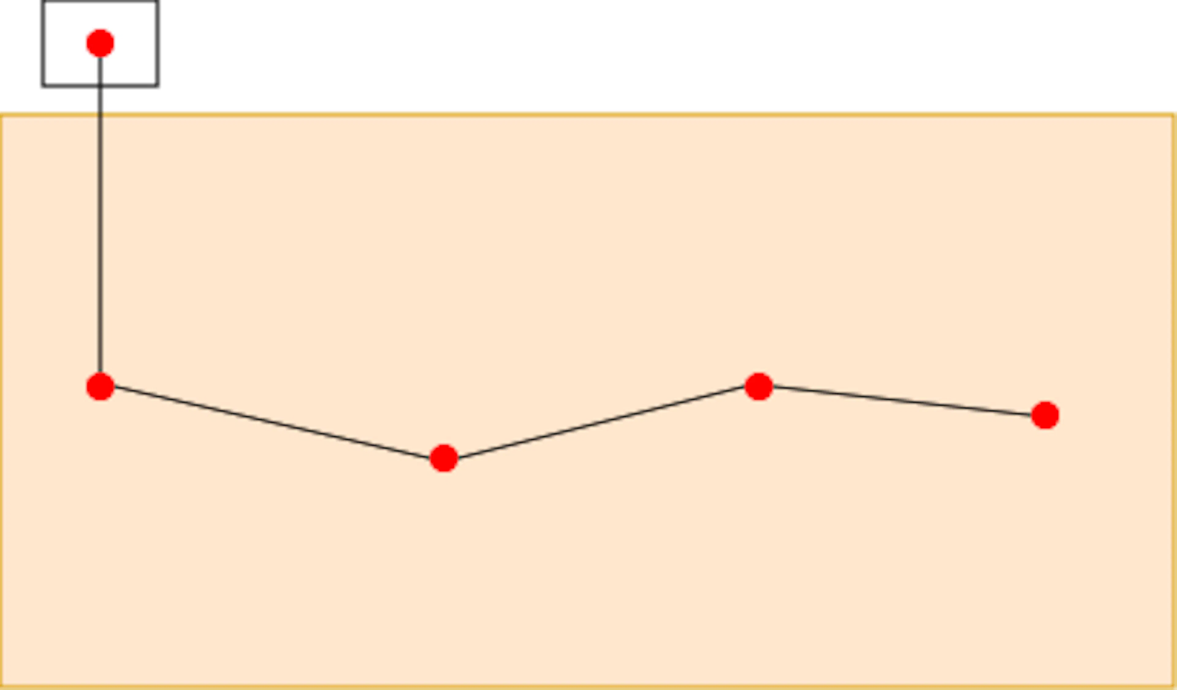
Settlement monitoring of specific locations that have a loose, or no, relationship to one another.
Custom built ASPs can be built to customer specification to accommodate the layout of your site.
Profiles
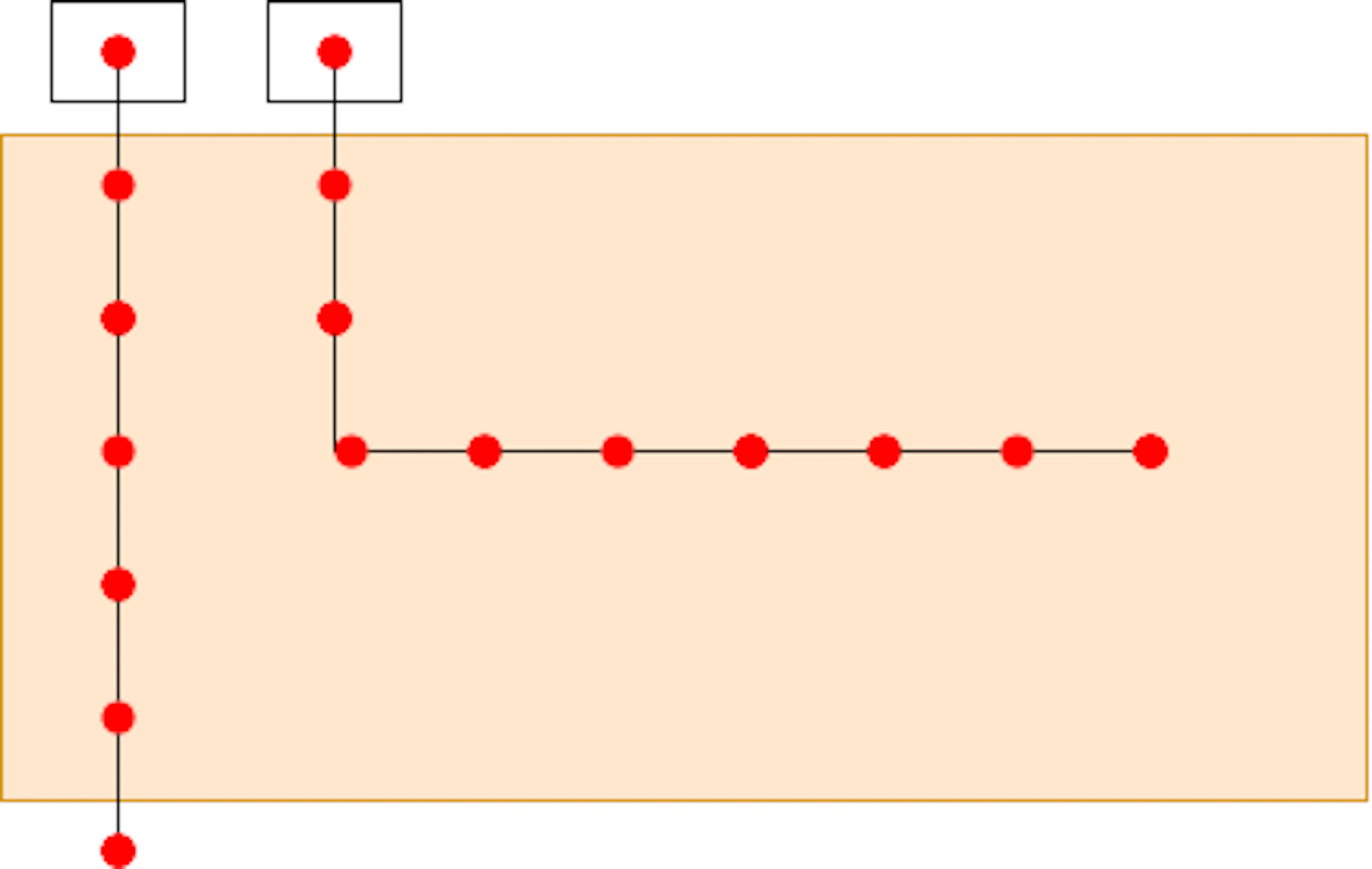
Settlement monitoring points in a linear alignment intended to demonstrate settlement relative to its position along or across a structure.
Density
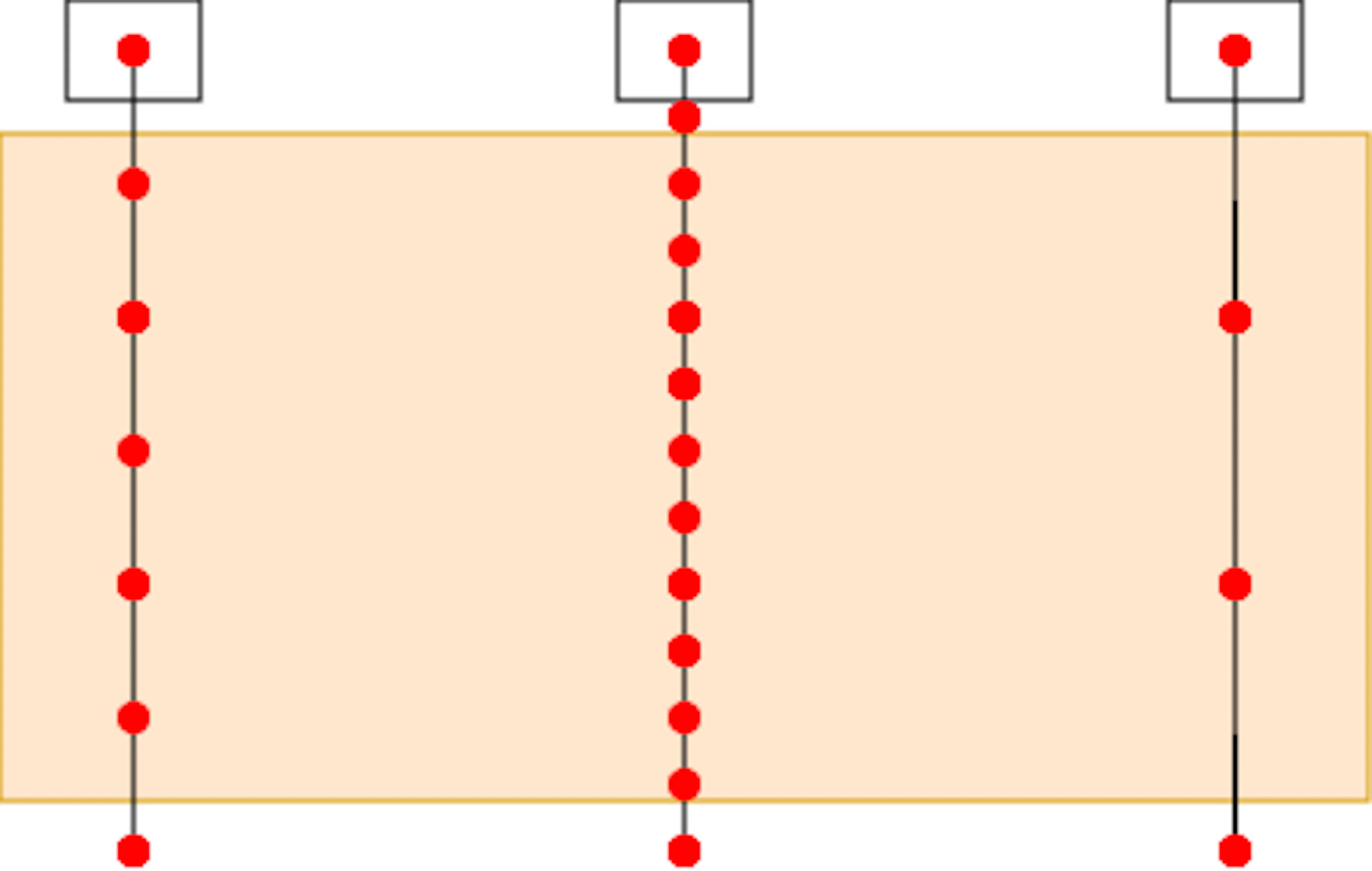
Where profiles are required, standard ASP systems are ideal, with regular intervals between sensors: 1m, 2.5m, 5m or 10m.
Distances
The ASP reference sensor sits 200mm from the start of the ASP system.
The maximum distance from reference sensor to the final sensor in the system is 145m long.
Within those 145m we can include up to 100 ASP settlement sensors.
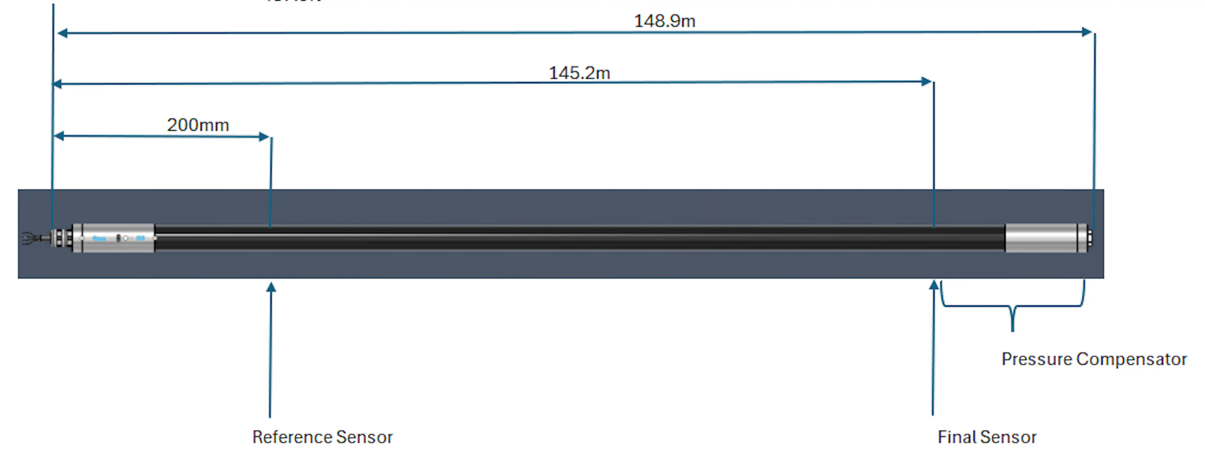
Space should be allowed at the end of the system to accommodate the pressure compensator. This equates to roughly 2% of the measured length, plus 0.5m
Use the ASP Length Calculator to calculate the total length of your ASP.
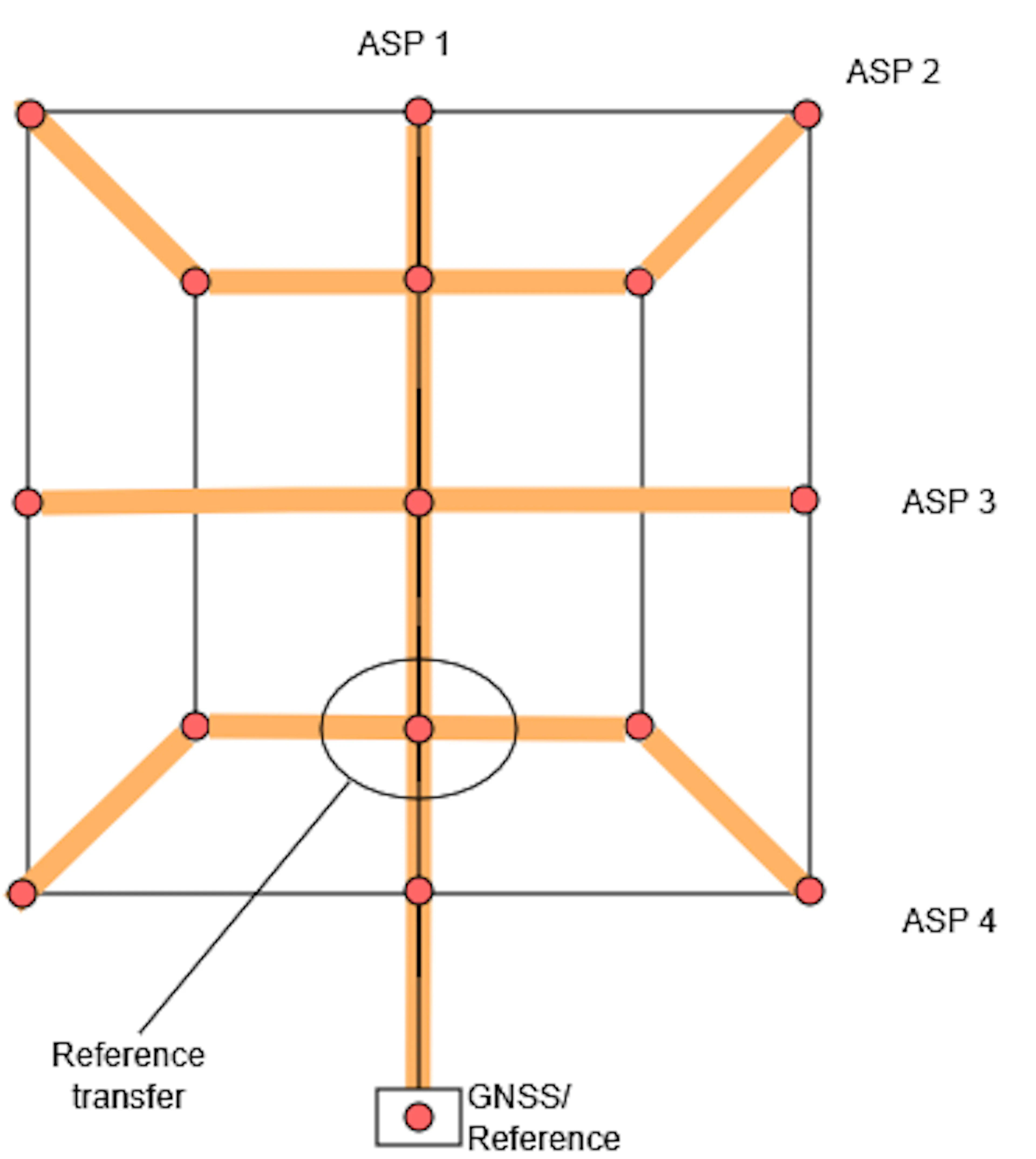
ASP’s can be overlapped and joined, to extend the distance covered by a single reference point
By joining two or more sensors in an ASP, control can be carried from one system to another, extending coverage without the need for additional external references. See Establishing a Reference for more details.
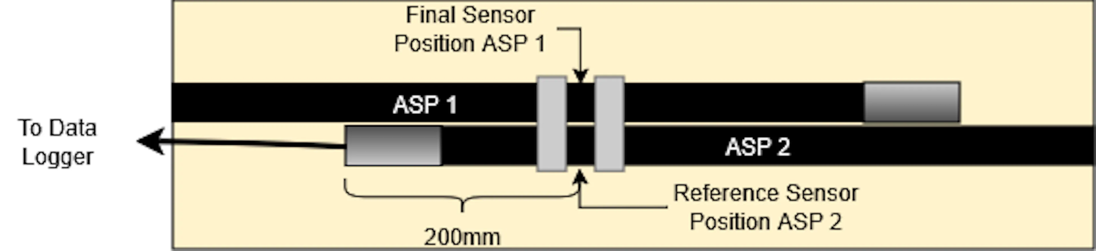
This can be done with any sensor in an ASP system, so it can be used for extending linear arrays, or creating grid patterns for broader coverage. See “data reduction” for more information.
Data Logging
System layout will determine the data logging requirements, which should be considered at the planning stage.
Like all Osprey-BUS products, the ASP has been developed in collaboration with the leading data logger manufacturers in the industry. There are some considerations to take into account when designing your monitoring scheme.
There are some limitations based on the data logger you choose, their power output and package size. The section on data logging covers the implementation, but here is a quick guide on the most used data loggers:
| Data Logger | Max No. Sensors | Max Read Frequency |
|---|---|---|
| Worldsensing G6 | 50 | 1 minute |
| Worldsensing G7 | 100 | 1 minute |
| Campbell Scientific Range | 100 | 1 second per sensor |
| WiSen | 100 | 5 minutes |
| Ackcio | 50 | 5 minutes |
Head to the "Data Logging" section of this guide for more information on each of the integrated systems.